2023-12-06 15:11:30
By


A motor is an electromagnetic device that realizes the conversion or transmission of electric energy according to the law of electromagnetic induction. Electric motors can be classified as electric motors and generators. An electric motor is represented by the letter M in the circuit. Its main function is to produce driving torque, as the power source of electrical appliances or various machinery. In the circuit, the letter G represents a generator. A generator converts mechanical energy into electrical energy.
Components of motors
The two mechanical parts of an electric motor are called the rotor and the stator. The two electrical parts are called the magnet and the armature, one attached to the rotor and one to the stator. These magnets, whether permanent magnets or electromagnets, generate a magnetic field through the armature. The magnetic field magnets may sit on the stator while the armature would be on the rotor but can also be the other way around.
Bearings
It is mounted on bearings. Bearings carry axial and radial load forces through the shaft to the motor housing, so the rotor turns on the shaft.
Rotor
The rotor is the movable part that gives mechanical power. The rotor is normally fitted with conductors carrying an electric current. The magnetic field of the stator exerts a force on the conductor, causing the shaft to rotate. Some rotors carry permanent magnets. Permanent magnets have high efficiency over a wide range of operating speeds and power.
Air Gap
The air gap between the stator and rotor allows rotation of the latter. The width of the air gap has a substantial influence on the electrical characteristics of the motor. As a rule, the narrower the air gap, the better the performance of the motor. This is because excess air gap reduces performance. On the other side, too small an air gap creates friction in addition to noise.
The shaft of the motor is outside of the motor to encounter the load requirements. In addition, since the load force is beyond the furthest bearing, it is known as a suspended load.
Stator
The
TThestator is placed around the rotor and usually includes the field magnets, which can be permanent magnets or electromagnets (wiring around a ferromagnetic core). These magnets create a magnetic field that permeates the rotor armature and generates a force on the rotor windings. The stator core contains many thin, insulated metal sheets called laminations made from electrical steel with properties such as permeability, hysteresis, and saturation. If there were a solid core, eddy currents would be produced, but this effect is minimized by stacking sheets. For AC motors supplied from mains electricity, the windings’ conductors are impregnated with varnish in a vacuum, eliminating wire vibration that would otherwise short out the insulation and reduce the motor’s life. Resin-encapsulated motors, used in applications like deep-well submersible pumps, washing machines, and air conditioners, have the stators’ windings enclosed in plastic resin to prevent corrosion and reduce conducted noise.
Armature
An armature is a wire wound around a ferromagnetic core. When current passes through the wires a magnetic field exerts a force (Lorentz force) upon them which causes the rotor to rotate. The windings are coils wound around a laminated soft iron ferromagnetic core, which when energized from magnetic poles.
There are two configurations that motors come in, with and without magnetic poles. In salt pole motors, the rotor and stator ferromagnetic cores contain projections called poles facing each other. Below the pole face, each pole contains a wire winding. The flow of current in these wires turns these poles into north and south poles. In a non-skewed pole motor, also known as a distributed field or circular rotor motor, the ferromagnetic core is a smooth cylinder. Its windings are distributed uniformly in slots around the circumference. The alternating current in the windings produces a continuously rotating magnetic pole in the core. Shaded pole motors have a winding around some of the poles that delay the phase of the magnetic field at that pole.
Commutator
A commutator is a rotary electrical switch that supplies current to the rotor. The commutator periodically reverses the current in the rotor windings as the shaft rotates. The commutator has the form of a cylinder on which several metal contact segments are positioned, and arranged on an armature. Two or more electrical contacts called “brushes” are made up of soft conductive material such as carbon, pressed on the commutator face. During rotation, this produces a sliding contact with successive commutator segments by the brushes for current supply to the rotor, with the windings connected to the commutator blades. Every half-turn (180°) of the commutator reverses the direction of the current in the rotor windings. Thus the direction of the torque applied to the rotor always remains the same. Without this reversal, the direction of the torque on the rotor winding is reversed every half-turn, thus stopping the rotor. Commutated motors have mostly been replaced by brushless motors, permanent magnet motors, and induction motors.
Motor Supply & Control
Motor Supply
As mentioned above, DC motors are usually supplied via an open-close ring commutator. An AC motor can be commutated using a slip ring commutator or an external commutator. It can be a fixed or variable speed control type and can be synchronous or asynchronous. General-purpose motors can run on AC or DC.
Motor Control
DC motors operate over a range of speeds by adjusting the voltage applied to the terminals, or by pulse-width modulation (PWM).
AC motors operating over fixed speed are normally driven directly from the grid or through a motor soft starter; AC motors operating over a range of speeds are driven by a variety of power inverters, variable frequency drives, or electronic commutator technologies.
The term electronically commutated is commonly associated with self-commutated brushless DC motors and switched reluctance motor applications.
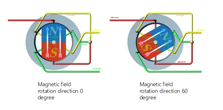
Principals
Electric motors rely on magnetic fields to operate. Magnetic fields can be generated by magnets or by windings around a magnetic core. The theory begins with an explanation of the magnetic force on a current-carrying wire exposed to a magnetic field. A magnet generates a magnetic field between the N and S poles. The magnetic field lines come out of the N-pole and enter the S-pole. This magnetic field is constant, there are no fluctuations in the magnetic field and it looks like a DC magnetic field.
When a current-carrying wire enters a magnetic field, the wire is subjected to a magnetic force and thus moves. The magnitude of the magnetic force depends on several parameters that will be discussed in this paper. First, the magnetic force depends on the current through the wire. That is to say, if the current through the wire is zero, then no force will be applied to the wire while the force is directly related to the current, Hence, the following equation can be written :
(1). F ∝ I
Where F is the magnetic force and I is the current in the wire. The other parameter is the length of the wire that sees the magnetic field. The relation of the magnetic force with the length of the exposed wire is also simple and can be written as:
(2). F ∝ l
Where l is the length of the wire. The last parameter is magnetic field strength which has a direct relationship with magnetic force:
(3). F ∝ B
These three parameters determine the maximum value of the magnetic force when the field is perpendicular to the wire. Therefore, any deviation from the perpendicular position reduces the force on the wire. This is because if one of these positions is deviated the magnetic force does not reach its maximum value. The reason is that an angle occurs between the magnetic field and the current in the conductor.
By considering all the parameters, the magnetic force can be computed by the following equations:
(4). F=B·I·l·sinθ
Now, instead of having one conductor in between the poles, a loop is considered. The loop can be of any shape. But for easy visualization, assume that it is rectangular. Then, each of its sides will carry the current and be under a magnetic force. The direction of that force can be obtained using the left-hand rule.
In this rule, the thumb is parallel with the magnetic force, the index finger shows the direction of the magnetic field, and the middle digit indicates the current’s direction. All these fingers are at right angles to each other. The magnetic force is zero if the current carried is parallel to the magnetic field in Equation 4. So, the magnetic force on BC and AD is zero.
Here, only AB and CD are magnetized. On applying the left-hand rule on the paths AB and CD, the direction of the magnetic force will be upwards for the path AB and downwards for the path CD. These two forces in opposite directions cause the loop to rotate. However, the rotation cannot be achieved because the direction of the current in the loop remains the same. In other words, when the loop is perpendicular to the magnetic field, it’s the position of most stability of the loop. There the upward and downward pulling forces cancel each other, hence there is no motion of the wire loop. For this problem, every half-turn of the rotation requires the direction of the current in the loop to be reversed for the wire loop to rotate. Additionally, inertia will help the wire loop continue rotating and pass through the position of stability.